
A PDF version is available here.
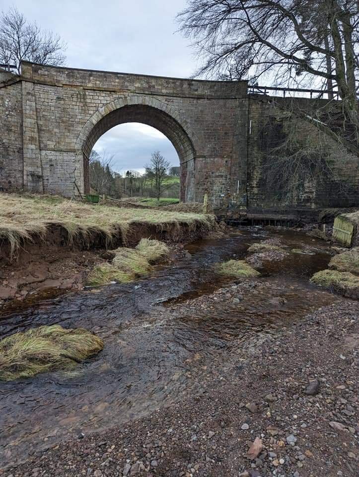
After Chester, where I found BoM 148, our Easter travels took us to good friends in West Linton, a rich vein to mine as far as bridges of the month are concerned. First up, the bridge carrying the A702, the main road from the west borders to Edinburgh, over Westwater (map).
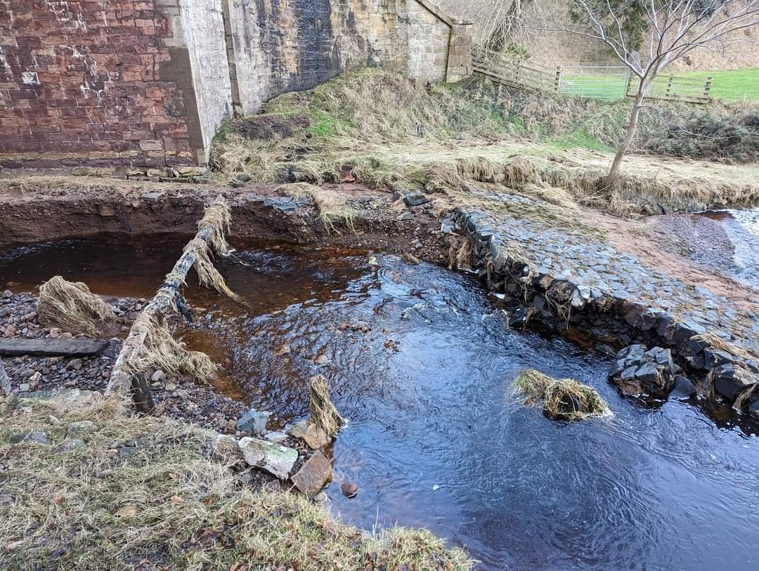
It is a fine bridge in its own right, but of special interest because it was closed by severe flood damage in January 2023. The repair work so far to the river is obvious here. I understand it isn’t finished yet.
Our hosts’ youngest was having a fine time administering first aid to the rest of the party, so I had plenty of time to look around and take enough photographs for a useful model of the soffit and elevations. Looking at the file times, from first to last of about 250 photographs was an hour. I built two versions, one with the ground included, the other with it trimmed out so it’s easier to inspect the masonry surface.
I would not have known, without the benefit of local knowledge, that the southwest abutment had been very extensively undermined. The local farmer, Hamish Dykes, captured the situation, and kindly agreed to me using his photographs of the immediate aftermath. Let’s look at that first.

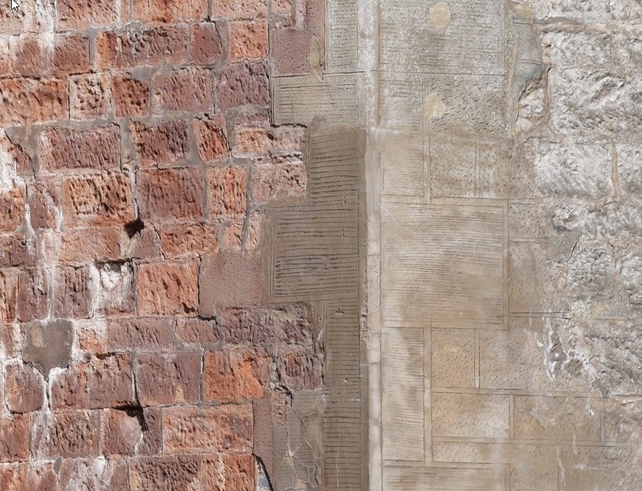
I haven’t traced any history of the bridge. The south side parapet carries a carved date, 1831 I think. This could be the date of the original construction, or of a widening or major repair. The clip is taken from a photo through a wide angle (24mm) lens from ground level, remarkable detail from a Sony A7Riii.
The first view is of the south side of the east abutment. The flood has cut deep, but not quite undercut the abutment here. The remains to the right are presumably of scour protection.
The real interest is to the west, where the water got right underneath the abutment, completely cleaning out the soil and leaving the bridge standing on the timber piles. Not a happy situation, but the piles held up!
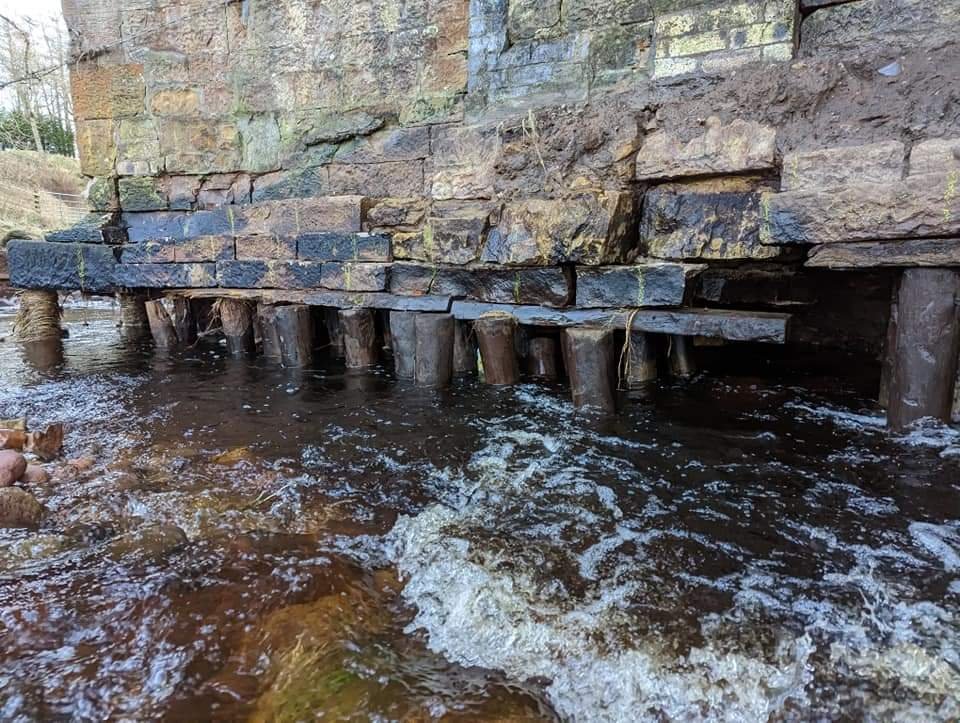
The damage spread a very long way back. The change in top of pile level is the back of the abutment, the rest is wing wall.

Stepping back, we can see that the scour extended most of the way to the back of the upriver wingwall. I don’t have a photo of the downriver side.
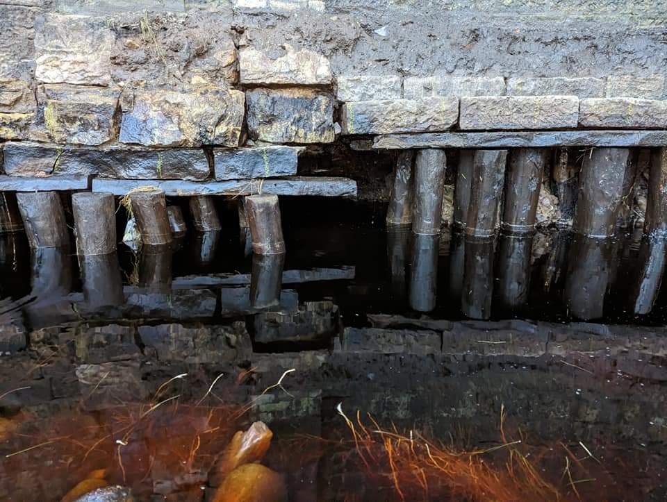
And lastly from this set of photos, a detail of the interface between the abutment and the wingwall. The perfectly cleanliness of the piles is striking.
Fast forward to April, and major work had been undertaken. If anyone can fill in detail here it would be great. From external appearances, the void under the west abutment has been flooded with concrete/grout, and the river channel defined by rock armoured banks.
I had no pole, so all modelling photographs were handheld from ground level. As a result, detail drops off with height, and upward facing surfaces are not captured. Details from high and low illustrate this.


The shadow over ledges is also a feature of terrestrial laser scanning and 360 photography. Filling in these details is one of many strengths of moving camera photogrammetry if photographs are obtained from height.
The model isn’t survey controlled; the photogrammetry software estimated level based on image metadata from the camera, which includes tilt. The result is as good as visual levelling, but it isn’t possible to examine level and plumb in absolute terms.
Photogrammetry is survey, and it follows the same rules. The model is linked across the river, making a closed loop, so relative geometry of the soffit and abutments will be pretty good. It is not closed over the road, so geometry of the spandrel walls will get more questionable towards the top, in addition to the loss of quality, which will appear in geometry as well as detail. Geometry error from lack of closure is mitigated by the plan curve of the elevations including the wing walls, which provides some stiffening of the model just as it does the bridge.
Caveats in hand, what can we see from the model?
The west pier appear to have been built in two parts. The north side has putlog holes at the springing, while the south side does not, and the colour changes around mid width. This change is not at a defined vertical line, but tapers out towards the southeast elevation at ground level. Was it a repair, rather than a widening?


It is perhaps too easy to think that the colour change is a change of stone. On the northwest elevation, there are marked changes in colour that appear to be a result of growth of different algae.
The string course at the springing shows a clear difference in slope. Absolute slope is uncertain, see earlier discussion, but change like this can be trusted.

The crack extends past the springing into the arch. It can be traced to the crown, continuing to trend slightly in the same direction.
The same pattern is found at the northeast springing.

This abutment face shows no obvious signs of reconstruction. Perhaps none of it was – or all of it. Sliding the plane down shows that the change in slope is present through the height at the southwest, but isn’t visible in beds at the northeast.
Close inspection of the string course suggests that it might be concrete to the southeast end of each abutment.
Three abutment corners show vertical cracking, or repairs in the form of stones replaced with mortar, or both. Interestingly the one with no similar damage is where the worst of the scour took place.


The northwest corner of the northeast abutment (far right above, repeated left) is least patched, but most damaged as it stands. Whatever the movement is here, it is causing significant damage in the cracks, with spalling of the crack corners and beyond, some areas filled in with mortar. The image to the right is the save view in false colour, highlighting changes in surface angle and thus local damage.

Cracks to the soffit inside each spandrel wall, and damage and old pointing above the ring over the crown, suggest some load related damage. This is common damage, of course. It is not a strength issue, but a result of differential movement between the flexible arch and stiff spandrel. Thus “strengthening” won’t do anything to help.

If we set a vertical plane on one elevation, then move it to the other, it is clear that the faces are not parallel. Note, right, how the plane (set on the other elevation) grazes the elevation at the near springing, but cuts well back at the far side. The divergence starts at the crown and develops to the far abutment.
The crack in the southwest abutment is fairly wide. It is filled with mortar, and has opened again since last pointing. We can’t tell whether the reopening took place as a result of the flood, or whether it was simply ongoing. The latter seems likely. It will be interesting to see whether it continues after recent works. Interesting enough, I think, that it deserves a few Moiré Tell-Tales.
There is some wireless monitoring equipment installed, which will be sending readings off site on a regular basis. Monitoring equipment is expensive (though probably not as expensive as its installation), and decisions and compromises must be made about what to measure. What is measured often gives an indication of concerns.

The most intensive monitoring is of the rear pilaster/buttress at the west wingwall, and the wall behind. The pilaster has 3-dimensional displacement measurement in front and behind, and a vertically oriented tilt beam at the same height. The wing wall just behind the pilaster has a vertically oriented tilt beams near the top.
The obvious concern here is that the pilaster has separated from the wall behind and moved out, and it can’t continue doing that indefinitely without collapsing. The damage below this instrumentation doesn’t look entirely fresh, so this isn’t all a result of the recent flooding.
The vertical tilt beam is measuring tilt very locally. It would be quite possible for this section to move outwards without changing tilt much, and certainly without showing any consistent change. Data from the tilt beam alone would not indicate what is happening here; the deflection measurement is needed.

The other area of intensive monitoring is on the right half of the southwest abutment face. There are 3 no. tilt beams here. All are placed on the same face, all horizontal. That means all 4 are configured to measure tilt across the bridge width. The tilt meters may be 3-axis, but the beam is designed to give an accurate tilt over a reasonable gauge length (1m is still quite short for many purposes). If I wanted to know what was happening to this piece of abutment, my inclination (see what I did there?) would be distribute tilt beams round the corner, and to have some vertically oriented, to get the best possible measurements in all 3 axes. Unless there is a particular concern about differential tilt between these pairs of beams, I would prefer longer beams.
Given the history of differential movement between the two halves of the abutment, I would really want measurement of the other side too, and across the crack.
Tilts are always only part of a story. I would also want to be able to track relative vertical movement of the four corners. That is a very difficult thing to do – more or less impossible using online monitoring. Robert Thorniley-Walker’s “movement gauges” are the only tool I’ve come across that might help. They allow measurement of differential movement to about 0.1mm using a standard level. The web site is down at the moment.