A PDF version is available here.
Grosvenor Bridge in Chester (map) has the honour, unusual among bridges, of being Grade I listed. We have relatives in Chester, who Bill visited as often as he could, so it is slightly surprising that he didn’t feature it before. A delightful if slightly curtailed visit as we travelled north to Edinburgh in the Easter holidays gave the opportunity to have a look.
In a sense this bridge is boring: there is little pathology, no intriguing diagnosis, it’s too big for a quick photogrammetric model, no one has (as far as I know!) proposed to fill it with concrete. But damn if it isn’t impressive.

It certainly warrants discussion as it was for a full 30 years the longest single span masonry bridge in the world, at 200ft (67m), after its completion in 1833. The Union Arch Bridge in Maryland, USA bested it by 20ft and in turn kept its title for 40 years. The Union Arch bridge shows some significant influences from Chester.
Note that this gap was not really for lack of confidence in masonry, but because technology for large spans had moved on. Iron Bridge in Coalbrookdale was already 50 years old.
Being such a remarkable achievement, I hoped to find a report in the ICE proceedings, and I wasn’t disappointed – the full text should be available to ICE members. As regretful as the ICE Council of the time may have been that it was not written directly by those involved, it is a fascinating report. The bridge is also discussed in Ted Ruddock’s wonderful “Arch Bridges and their Builders, 1735-1835”. That in turn refers to the younger John Rennie’s Presidential Address to the ICE in 1846.
The bridge was originally designed by Thomas Harrison, but by the time construction started he was 82, and stepped down. Jesse Hartley took on the role of clerk of works, the contractor was James Trubshaw. Both Telford and George Rennie gave advice at different times between concept and completion – I’m not absolutely clear on whose behalf. Somewhere I have read of an engineer taking over work from Harrison on condition that he would be free to make whatever changes he regarded necessary internally; this was presumably either Rennie or Hartley, but I haven’t managed to find the reference again.
Telford is credited with finding a better site, after the original site proposed was found to provide inadequate foundations for the abutments. Ted Ruddock has Telford undermining an application for a loan by stating that the site was inappropriate and the span unnecessarily long – was this complaint about the original site or the final?
John Rennie, in his 1846 Address, states that his older brother, George, “equilibrated the arch, and gave the proper dimensions of the voussoirs and form and dimensions of the abutments, the mode of constructing them, and designed the centre, the original model of which is now in [the ICE] gallery”. Ruddock reports Rennie’s advice that both abutments be founded on rock. The Proceedings report states that this was done, though the deeper abutment is not shown in the plate.
A drawing titled “Modification of Mr Harrison’s Design for Chester Bridge” from the Rennie Collection at the ICE (thanks Carol!) shows the town abutment with no piles and the far abutment entirely piled, with not even the piles reaching rock. Comparison with the plate from the Proceedings, further below, also shows several differences. Perhaps this drawing predates Rennie’s conclusion that piling was inadequate.

Drawing from Rennie Collection, courtesy of the Institution of Civil Engineers
Founding the far abutment directly on rock would indeed have required a large excavation and considerable additional cost. The rock is higher on the town side of the river, but piles were still required at the rear where a fault results in the rock surface dropping away steeply. This was perhaps discovered during construction and thus isn’t shown on the coloured section above. These piles provide vertical support to the mass of masonry and fill at the rear of the abutment; the main force from arch thrust is expected to come down directly into rock in front of this.

Drawing from 1846 Proceedings, courtesy of the Institution of Civil Engineers
The structure as built carries sloping beds into the abutment and down to the foundation, a classic Rennie feature.
Ted Ruddock reproduces a drawing from the Telford Collection at the ICE, presumed to be Harrison’s, which shows a more “normal” abutment of horizontal beds on vertical piles.
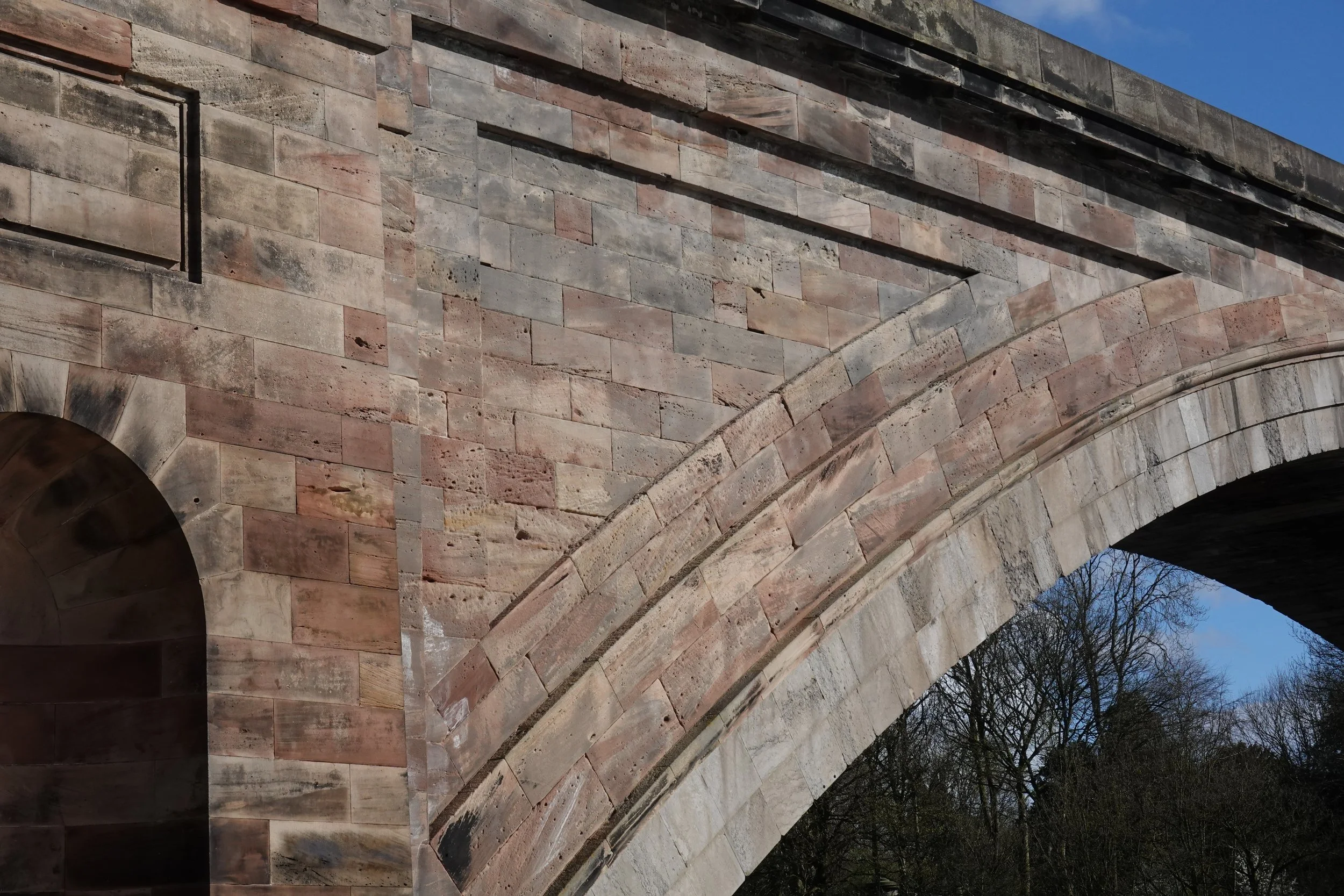
It is apparent from a glance at the bridge that the stone used in the part of the ring nearest the intrados is different from the rest of the exposed stone in the elevation. From the Proceedings report, this is Anglesey “Marble” (limestone). Inspection shows that this is only used for the stones at the edge of the ring.

Less obvious (I didn’t notice, but we didn’t get anywhere near them) is that the river faces of the abutments are of granite, brought from near Castle Douglas. It is stated that this granite is also used for the first two courses of voussoirs in the arch – from the photo above, it looks more likely that these are limestone.
The rest of the visible stone is from two quarries in Cheshire. The internal stone was mostly quarried adjacent to the bridge: just as in brick construction, lower quality material was used internally. All of the Cheshire material is New Red Sandstone.

It may not be visible at reduced scale, but the sandstone in this detail shot is speckled with tiny reflections from the bright sun.

The ICE report dwells on the centring, interesting on a number of counts. One – of great interest to the contractor - is that its design carefully avoided damaging expensive timber, ensuring that it could be sold locally after construction. The net cost of the centre was £500, £48,000 in 2023 prices according to the BoE inflation calculator.
The centre (visible in the half section above) used fans of straight timbers, loaded (apart from self weight) entirely in compression, carried on intermediate temporary piers in the river. These were the only heavy, long timbers; the remainder of the centre was relatively light framing. That allowed for the minimum damage mentioned. It also apparently allowed construction of the arch to run in parallel with completion of the centre. The claim is made that half of the arch was complete before the centre was finished. I suppose that means a quarter width from each abutment built before the centre was complete in the middle.
Another novel feature is the use of a pair of folding wedges under each voussoir. This was different from the more normal practice of placing folding wedges where the centre is supported, so the whole centre, or at least large sections of it, are dropped as a piece.
The suggestion is that this proliferation of wedges allowed the haunches to be lowered ahead of the crown. The intention was to lower slowly while the mortar was still wet, giving time for joints to adjust as the shape settled.
Recall that John Rennie, in his 1846 Presidential Address, claimed that George Rennie was responsible for the novel centre design. He also stated that Hartley and Trubshaw “worked out the details, and carried the whole into effect.” The ICE report has it that Jesse Hartley attributed the centre “exclusively” to Trubshaw. The use of “exclusively” is suggestive of dispute. John Rennie would surely have seen or heard the report. Was he using his platform to correct the record (as he perhaps saw it) in favour of the family? His description still leaves open a wide variety of possible divisions of labour, and no reader of the Proceedings would imagine “working out the details, and carrying the whole into effect” to be a small matter.
Other notable features from the construction are two uses of lead. First, wedge-shaped pieces of lead were placed in the joint just above the springing at each end, 1½in thick at the soffit and tapering out to nothing at the extrados. These would compress as the arch was loaded and the shape adjusted, ensuring good bearing through the depth, and avoiding the hidden extrados crack that is normally expected on decentring.
Sheets of lead were then placed in every joint at the intrados up to about the third points of the arch, again ensuring that where the thrust might be close to the intrados, the stress will not be too concentrated. The stones were still chamfered at the intrados to avoid spalling.
Lead came into play again at the crown, where three strips of lead were placed on the upper sides of the stones each side of the crown. The keystone was lubricated (“besmeared”) with a mix of white lead and oil, and driven in with a pile driver. Doing this would drive up the horizontal thrust and lift the crown, even before the haunches were lowered on their wedges.
The net result of these measures was that the crown dropped by only 2½in, all joints remained closed, and the no “derangement” of the form was perceptible.
The crown drop is reported to 1/8in. Careful measurement of changing shape much beyond simple crown drop is implied by the complex decentring process. No detail is provided of how this was achieved, but measuring to this sort of precision would have been quite possible with a water level long before 1830.
I’ve seen plenty of laser scans that wouldn’t allow this. It would be fascinating though to closely interrogate a good quality laser scan to see what the settled shape is and how it differs now from the design curve.
One thing I missed on my visit – so I will have to go back soonest – is that a scale model exists, itself grade II listed, embedded in the city wall embankment near the castle. The listing text reads, “Scale model of the Grosvenor Bridge, Chester City EM (qv), carrying Grosvenor Road across the River Dee. Probably made in 1826 to demonstrate to its sponsors the bridge built between 1827 and 1833. The model is approx 5.5m long and nearly one metre high. The model was moved from south of Raymond Street to its present site in the 1980s.” There is a photo on the main list entry page. Given the calculation undertaken by George Rennie, I suppose this is as suggested an architectural model rather than a structural one.
In his 1846 Presidential Address, in discussing Grosvenor Bridge, John Rennie notes that, “A proper theory of the equilibrium of the arch, which shall satisfy all the conditions of the question, when applied to practice, may be said to be still wanting, though much valuable information may be derived from the scientific works of Hutton, Attwood, Moseley, Gwilt, and others, on the subject.” It is unfortunate that he didn’t itemise “all the conditions of the question.” Did he have more in mind beyond stability and abutment thrust? Barlow presented his seminal paper to the Institution in the same year, which demonstrated with physical models that the many possible lines of thrust allowed by theory were equally valid. What tools did George Rennie feel he lacked in looking at Grosvenor Bridge?