

A PDF version is available here.
We stop as frequently as opportunity allows with friends in Walkley, Sheffield. While there, I have enjoyed several walks in the Rivelin Valley, a lovely woodland valley packed with industrial archaeology, very close to the city.
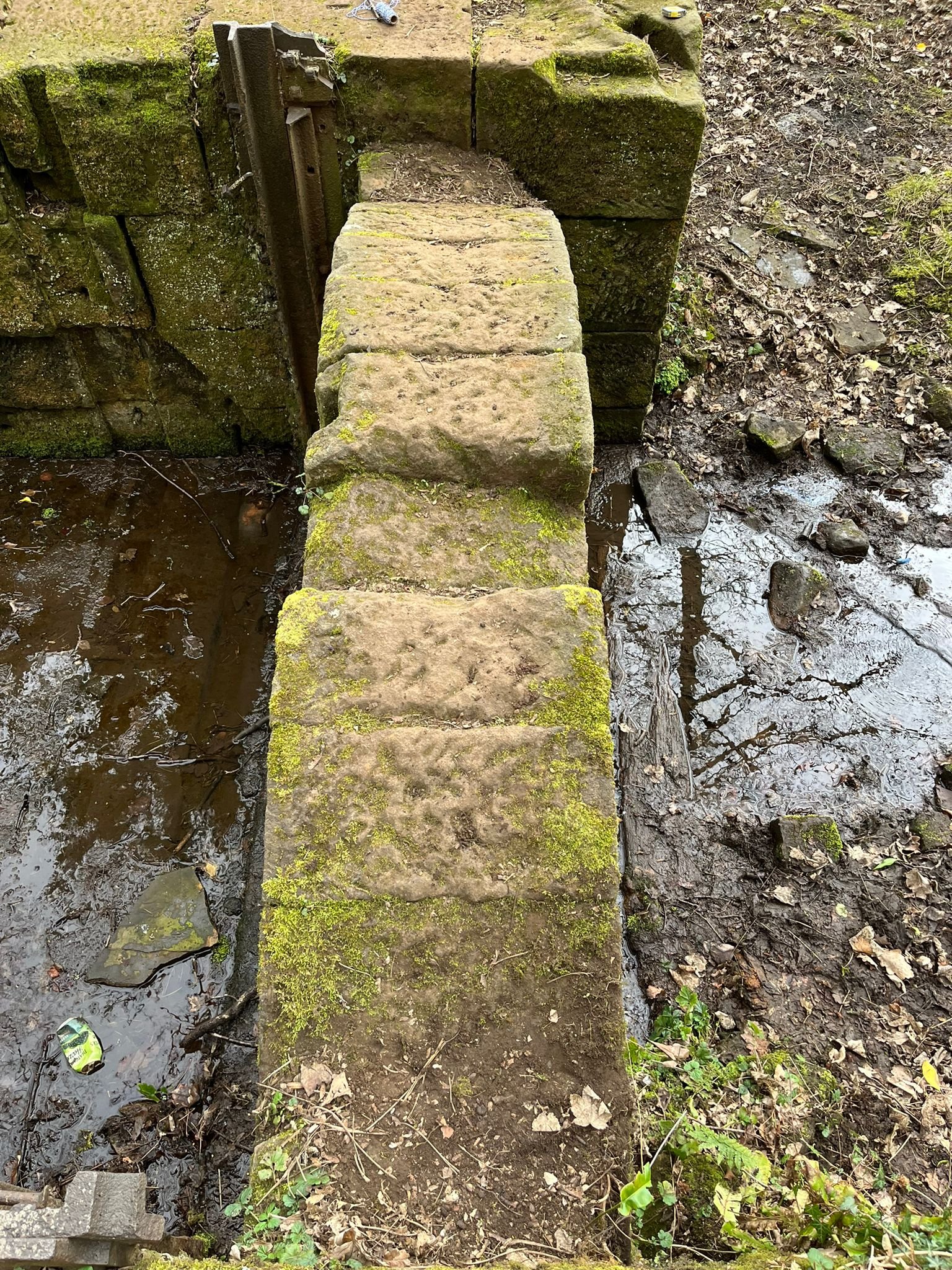
Rob, out on a walk recently, took this photo and sent it to me with the comment, “Even I can spot the defect here.”
As odd as this is, it is obviously also fine. It’s a defect, and in a general sense could be regarded as damage, but it is not damage in a structural sense, and as far as I can see there is no sign of distress (related or otherwise). These distinctions were highlighted by Patrick Sparks in a twitter thread last summer.
The question that sprang to my mind was: how? What set of circumstances allowed or caused a single stone to drop relative to the remaining arch on either side?

A bit of context. We are at the site of the Roscoe Wheel, which is shown in the middle of the 1850s OS map and also google maps if you zoom in close enough. The photo of Sam with string above shows the silted-up pond that fed the wheel. The original shot shows a drop into the wheel pit, now also part filled. Right, we are looking downstream, at the filled wheel pit and, just visible, the entrance to the tunnel that carries the flow back to the natural river. The valley is a seemingly endless series of these diversions and returns. Look around on the 1850s map and see the number of wheels marked.
I gather the valley doesn’t stay lovely of its own accord: the Rivelin Valley Conservation Group do a lot of work to keep it that way. They have a page about the Roscoe Wheel.

I asked some questions, and – for no particular reason but interest – for an estimate of span, width, and depth. Rob and Sam kindly made a project of it, and went out again, armed with some string and a tape measure, and took some additional photos. Here, Sam is getting set up for a rise measurement, waiting for his assistant to get back from taking a photograph.
Sam is of a mathematical temperament, and I asked Rob to see if he could think of a way of measuring the rise. He suggested measuring up from the ground at the springing and crown (not using those words, I’m sure). Not bad. Some further discussion highlighted the challenge of uneven ground, and the alternative of measuring from a string line was developed.

The dimensions they came back with were 2800mm span, 455mm rise, 300mm ring thickness. The dropped stone is about 90mm low, with a possible slight difference in offset on either side. (I couldn’t stop myself questioning whether the rise could be measured to the nearest 5mm, because what are friends for.)
Those dimensions are interesting. In old money, as Bill would have said, rise and ring thickness are 1.5ft and 1ft, which are very plausible. But the span at 9.19ft seems a bit long. 9ft span, 1.5ft rise gives a neat 6:1 span:rise ratio and an equally neat 7.5ft radius. Very likely. The extra couple of inches in the span could probably be explained away: a bit of tape sag, the abutments have relaxed slightly, some measurement uncertainty.
That’s not quite the end of the story, because the photo shows the measurement being taken at the accessible extrados, where we would expect to see a lower rise than at the intrados. I think the difference may be nearly 100mm. Could that low stone lift the arch enough to cancel that out? I suspect not but I … must … resist … getting further into the geometry of this right now.
The real question was how? The movement here is a bit like taking a tower of blocks, and displacing a single block in the pile, while those below and above remain in place. Like Jenga, but with a single piece at each layer.
If you wanted to do that, your options are to hold the blocks above and below back as you push, or to tap the piece you want to move very sharply, so you overcome static friction and get some movement, then stop before the blocks above start travelling with you.
Now exactly this was probably done sometimes when building arches with dressed stone voussoirs, with the classic oversize keystone being tamped in. Dropping a heavy weight on the top of the stone would drive it in. Doing so would very slightly lengthen the arch, lifting its weight off the centring. But this isn’t the crown voussoir, and isn’t oversize, and I think we can dismiss the possibility that it was intentional.
I don’t know how likely flooding is to pass this way, off the main river as it is. Perhaps more so after abandonment but before use of the valley for recreation took off. A flood would lead to some buoyancy, but water alone certainly wouldn’t remove all thrust from the arch to allow a stone to drop. Debris forced underneath the arch would be more likely to result in displacement at one joint, or perhaps an upward movement of a stone.

Looking again at the previous photo: there was no real need for a bridge as such at this location, it was not a long walk round to cross below the wheel pit over this tunnel. I didn’t notice when I received the first photo, but there is a carved notch in the stone at the crown, clearly carved out to receive something. It’s clearer in the photo to the left, which was taken to show the offset across the full width. The arch, with its notch, are evidently part of the flow control for the wheel. Perhaps the works was able to transfer load from water onto the arch in some unusual way, letting the stone drop.
If anyone has any theories, please do let me know in the comments section below!