
A PDF version is available here.
Well, that is quite a turnup. The fill is to be removed from Gt Musgrave. Still, having made a detour to Melkington to see one of the other candidates for infill, I might as well report on it. The journey north via Coldstream took me on a long-remembered route, at some cost in time. The site is quite overgrown so I couldn’t get the broad shot I would wish to start. Here is the best I could do.

Skew bridges, road over rail, are usually built on standard square span centres except when the skew gets so severe that setting it up becomes expensive and complex. If the standard bridges are segmental (as here) square centres will result in a stretched, elliptical skew span. I suspect that this view is showing a squashed ellipse on the square which means circular on the skew.
Turning to the acute edge shows how skew the bridge is. Previous measurements say just over 50 degrees.

Also in the corner picture we see mud runs down the line of steepest slope. I am not sure where they are coming from. Perhaps I will be able to see in the model so now might be a good time to introduce that. I spent 20 minutes at the bridge and took 230 photos from the ground using a Sony A7Riii with a 24mm G model lens. The bits that appear white in these images are where the camera couldn’t see. Quite a modest pole would have overcome the problem on the elevations but the state of my hands after Chemo mean that I cannot manage a pole and trigger etc.

This orthographic elevation suggests that the arch is circular on the square, despite the very high skew. A square view of the spandrel wall looks rather flatter, with the curve increasing slightly towards the springing. Among other things, notice here how the voussoirs are lozenged shaped. This is what you get when you cut through a spiral on the skew.

Notice how the voussoirs go lozenge shaped towards the springing.
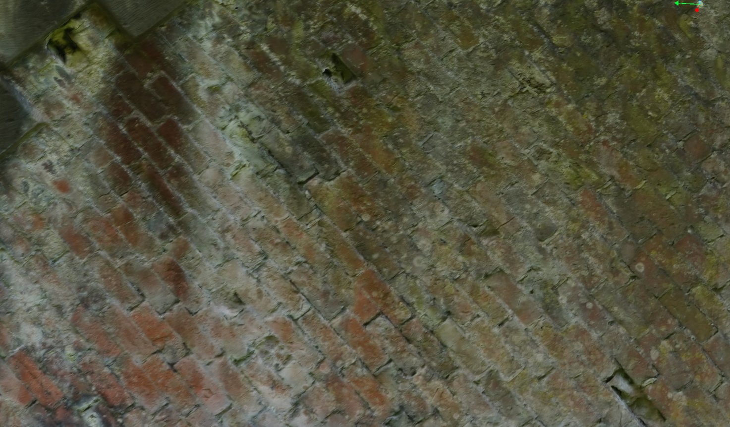
One thing I was looking for was mortar loss. The assessment that NH relied on to condemn the bridge said up to 100mm and reduced the whole ring by the full 100mm. I have examined the soffit closely and found negligible mortar loss. In the image below are 3 badly weathered bricks, one top left, one top centre and one bottom right. These were the only such bricks found. They are isolated, and certainly don’t justify discounting a full ring.
Also in the analysis, there was no consideration of backing. Were this bridge being considered within a network owned by a regional council, it would be quite unacceptable to take the most conservative assumption at every point. What the bridge owners need is a reasonable assessment which allows them to prioritise work. If a bridge in this condition were slated for immediate repair, what other structures would be pushed down the list?
Let’s look at the numbers. The assessing engineer quotes a skew span of 14.35m and angle of 50.47 degrees. That gives a square span of 9.134m or 29.97ft. Given the difficulty of measuring skew spans It seems most likely to be a 30ft square span.
The rise is given as 2.39m or 7.84ft. The arch will surely have sagged a little on decentring. Striking a horizontal plane through the model certainly shows a dip to mid span.

The most likely original shape seems to be an 18ft radius, giving a rise of 8.05ft, 2.45m which would mean a sag off the centre of 64mm.
Putting those dimensions into Archie-M and auto-running loads from BD21 (because the assessment was done before CS454 was published) the worst case is a two-axle bogie with impact.

Adding a modest amount of backing makes the bridge more than adequately safe.

There is no sign of a weight limit on the road and the previous assessment was done in 2009 so we can assume that this A road has carried many full weight vehicles in that time. It has been thoroughly tested for such loads.
I need to sign off as I am several hundred miles from home, unable to drive myself and my driver/daughter has just gone down with covid. It is worth looking at a couple of details though.
First, how beautifully dressed the stone is.

At the corner above, the skewback naturally forms a solid piece for the arch helix to sit on. At the opposite corner, construction is much more complex, with a double voussoir cut into the single stone.
This picture also shows how the voussoirs project about 25mm below the brick arch. That must have made for some interesting centring.

I was intrigued that the buttress seemed to be cut in rather than bonded.

And finally, I love this detail of the string course, sloping continuously down to the outer edge.
OK, time to give the sick some attention. Hope things are more together next month.
