
A PDF version is available here.
This month we are looking at a bridge in the Eden valley, Cumbria. Surely most readers will be aware of the issues here because they have featured in both the national and technical press. Here is a picture from before the current fracas.

Below we see the infill work in progress. Notice that the car wishes to occupy the full width. It would be very difficult to get two trucks side by side into the 5.63m width between parapets.

And here is how it looks now.
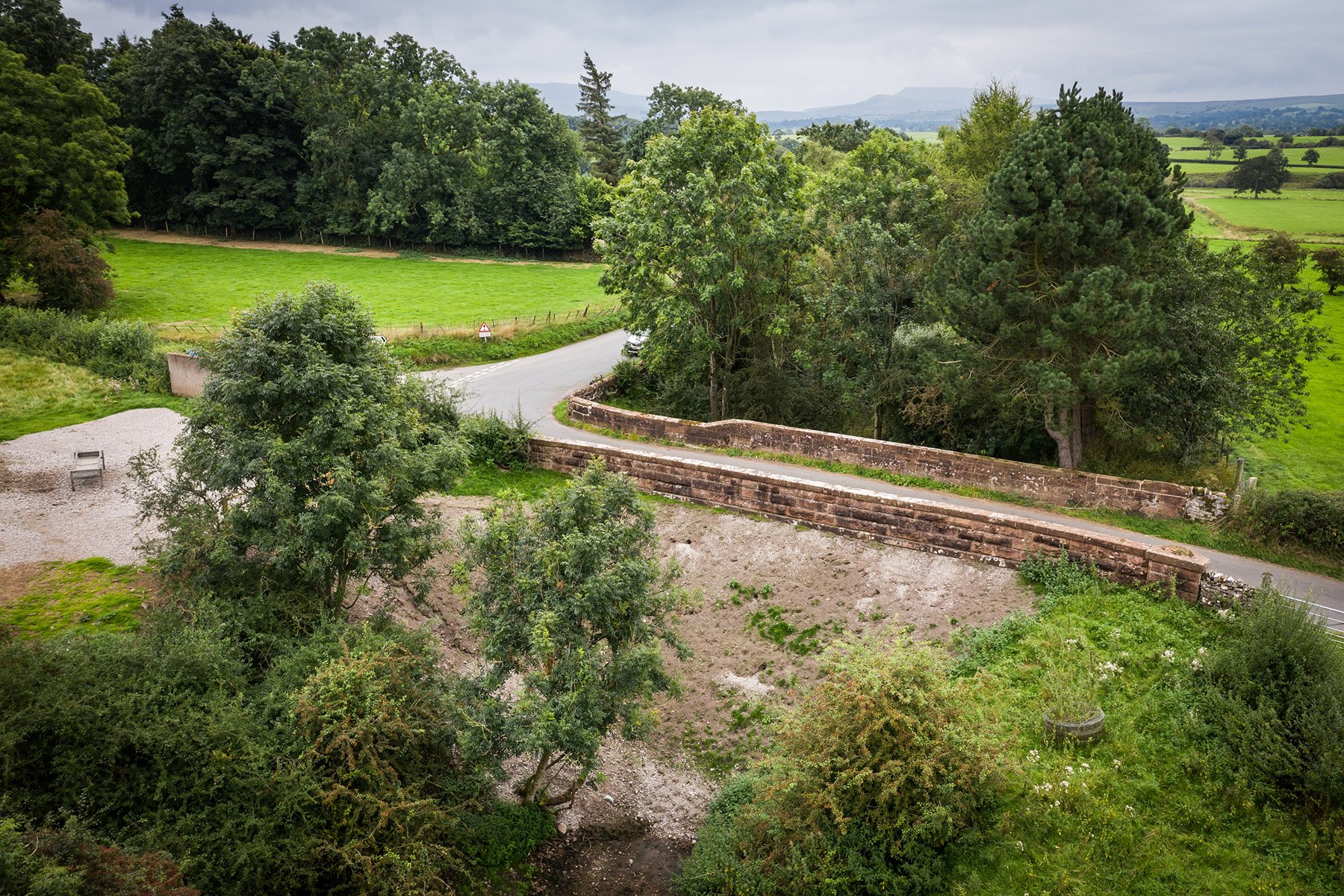
The bridge is skewed by about 13 degrees. You can see that in the first picture where the fences have been built square to the abutments.
“The bridge” sent some dimensions via twitter.
All dimensions – whether measured yourself or, as here, from an unknown source – need to be checked carefully for sense.
We can estimate the skew angle from the span, width and diagonal dims using the cosine rule. Depending on the triangle chosen, the skew comes out at 12.7-12.8 degrees, so nicely consistent.
With skew bridges, it is important to establish whether the centres were placed skew or square. On over line railway bridges, the answer is usually square, as the centre defines the loading gauge, and the same centres will be used for many bridges along the line. The skew span as measured, converted to the imperial measurements used at the time, is 27.6-27.7 feet. That is most unlikely to be the span of the centre, which would normally be a round number of feet or, occasionally, a sensible number in fractional feet.
With a skew span of 8450mm, the square span would be cos(13)*8450 = 8230mm = 27 feet. That’s quite short for a twin track railway span, but not impossible. Given the round number and the redundancy of measurement we have reasonable confidence in it.
The dims give levels at springings, crown and quarter points. We don’t know how these levels – to the nearest millimetre! – were obtained. Crown and quarter point rise can be obtained from these. Quarter point rise measurement is notoriously difficult, because a slight error in the location of measurement results in a large error in the rise. The rise, found by subtracting the interpolated springing level from the crown level, is 2300mm, or 7.5 feet. In fact it is slightly over 7.5 feet, which is a little surprising, as the arch will normally drop at de-centring. 27/7.5 gives a span:rise ratio of 3.6, which again is unusual. 7.5 feet would be a common rise for a 30 foot span, giving a 4:1 span:rise ratio.
The quarter point rises reported are 2020 and 1990mm. These aren’t expected to be meaningful in feet, so staying in metric, the height of an 8230mm x 2290mm semi-ellipse at x=2060mm (the quarter point) would be sqrt((1-2060^2/(8230/2)^2)*(2290/2)^2) = 1980mm. So the shape is within measurement error of a true ellipse.
So, although the span of 27ft is unusual, as is the combination of a 27ft span and a 7.5ft rise in a true ellipse, the dimensions are consistent enough to provide reasonable confidence in the shape of the arch.
Taking a closer look at the soffit is interesting.

The joints all seem to be tight and straight. Loss of mortar could not amount to much and would certainly not impact on the bridge capacity. The water marks suggest backing at least to the sixth voussoir from the end but more likely the ninth, which would be more or less level with the arch crown intrados. On that basis I would suggest the bridge would suffer no damage from any AWR vehicle. The worst case would be as shown below.

Or with impact
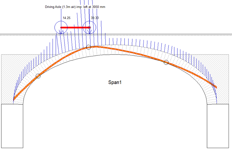
In a rural area like this, it is extremely unlikely that the bridge has not been subject to maximum standard vehicle loads. Indeed, some un-sprung tractor trailers might produce more onerous loadings. If the bridge were to suffer damage from normal traffic it would surely have done so already.
Nothing in the photographs I have seen suggest that there is any underlying reason for concern. The Archie-M pictures above would normally be accepted as evidence that the bridge has ample capacity. I haven’t seen it in the flesh, of course.
But there are other issues. There is no possibility that the infill produces an enduring tight fit support for the arch. If the loading, and associated movement, is capable of damaging the bridge, that damage will continue and will manifest in breakup of the pavement. The damage will be impossible to repair.
The bridge seems to have been condemned on the basis of measured loss of mortar with a figure of 170mm quoted. That particular measurement was in a perpend joint in the arch which was probably never properly filled anyway and has no consequence on capacity. In the bed joints, the loss is patchy with a maximum measured value of 40mm.