
A PDF version is available here.
This record is a result of one of the endless teases from Network Rail. The RAM concerned was suggesting a long term commitment of at least a day a week on his bridges and this was one at the top of the list so I diverted on a holiday and left Sue sitting in the car for an hour while I took photos. I took a lot because it is a complicated bridge and it turned out when I tried, that there were enough to build a decent model, despite this was long before we had succeeded in building models. In the end the job was passed to Matthew Gilbert, which is fine, and he had the benefit of being much closer. But there is a lot to see here so why I don’t post my take on it all.

It is a tiny bridge and the skew would make little difference if it were not for the height, and lack of support, of the abutments on the acute corners.
First though, the location, which is here. If you follow that link you will see that the two tracks occupy about a third of the width, which means there is quite a substantial embankment on top and that extended parapet/spandrel shows that the earth has been flowing towards the edges (and, no doubt, being replenished from the top).
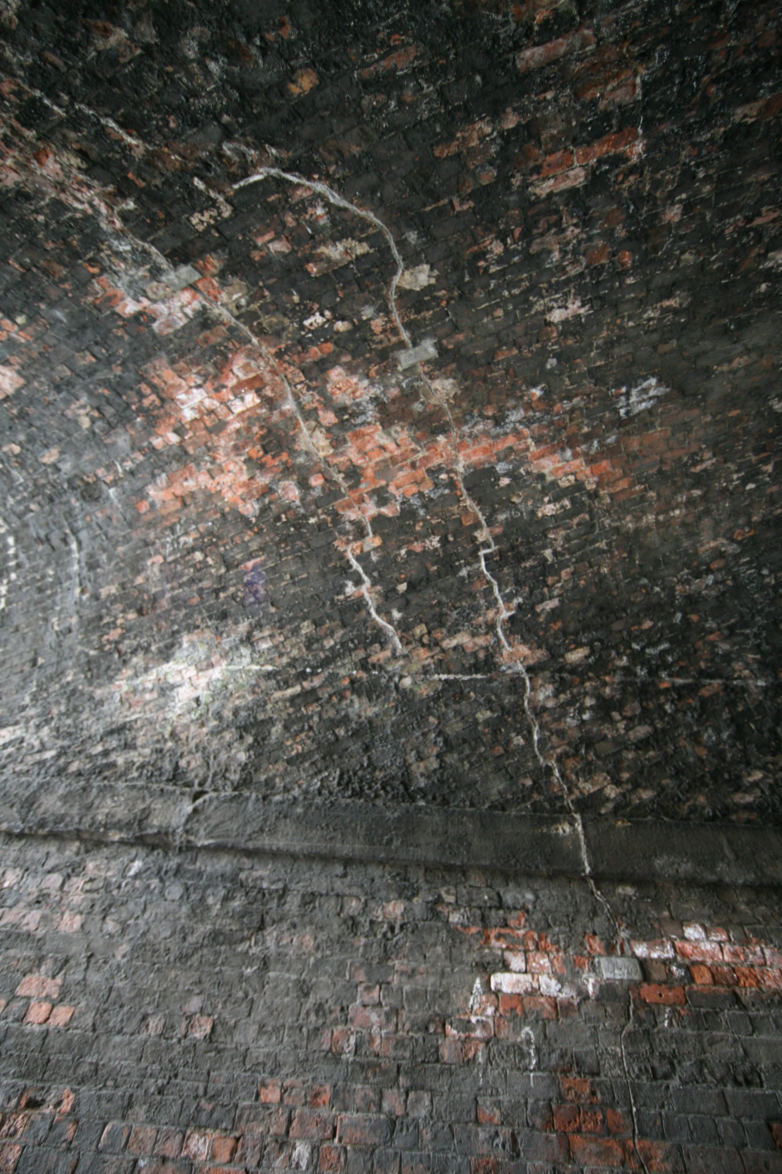
I was intrigued by the crack patterns at the time and have become more so since. So let’s start with an upview.

Notice how the cracks are all pretty much along the skew line. I imagine that the ones near mid width are actually a result of the whole thing sagging under the rather greater dead load at mid width. I have seen such cracks in a number of other bridges.
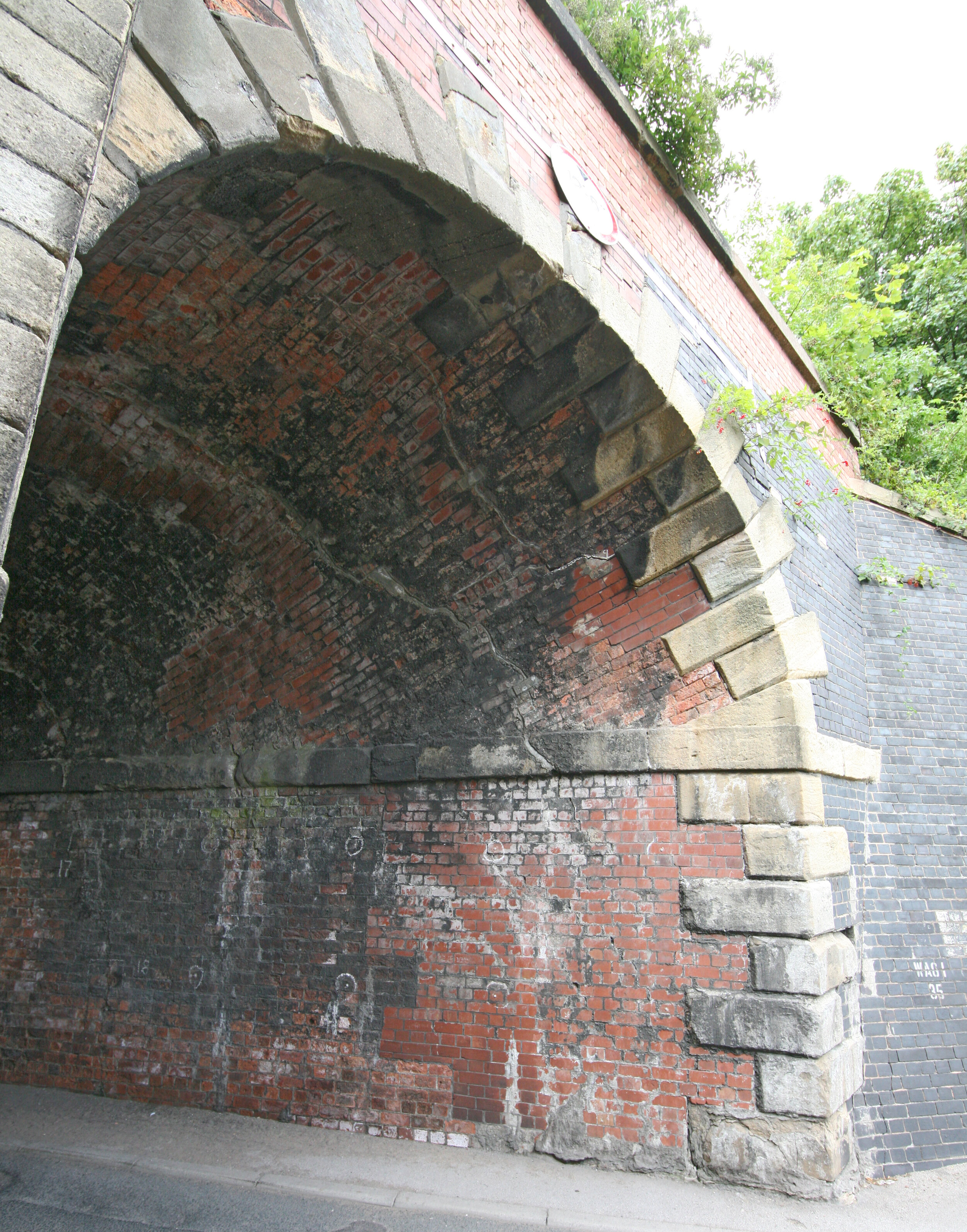
Let’s look a bit closer at the end elevations, though.

That shape is a bit weird. At the right, we are essentially looking at the back of the abutment. To the left we look straight along the string course which sweeps forward and down towards the end. At the arch crown you can see the sag mentioned above. Looking from the other end the pattern is similar.

Here we also see the full elevation and the distress in the spandrel walls and the end of the arch itself.
Enlarging the upward view locally shows us a little more of what is going on here. There is quite a lot of newish brickwork and some complex cracking.

If I push that pic a bit we can see just a little more detail. If I ever get a chance to go back I will use a better camera and, particularly at the end here, capture a few more pictures.

The mid width cracks are also worth a closer look.

The original photos here are better than the model (that wouldn’t happen today). The cracks run down into the abutment.
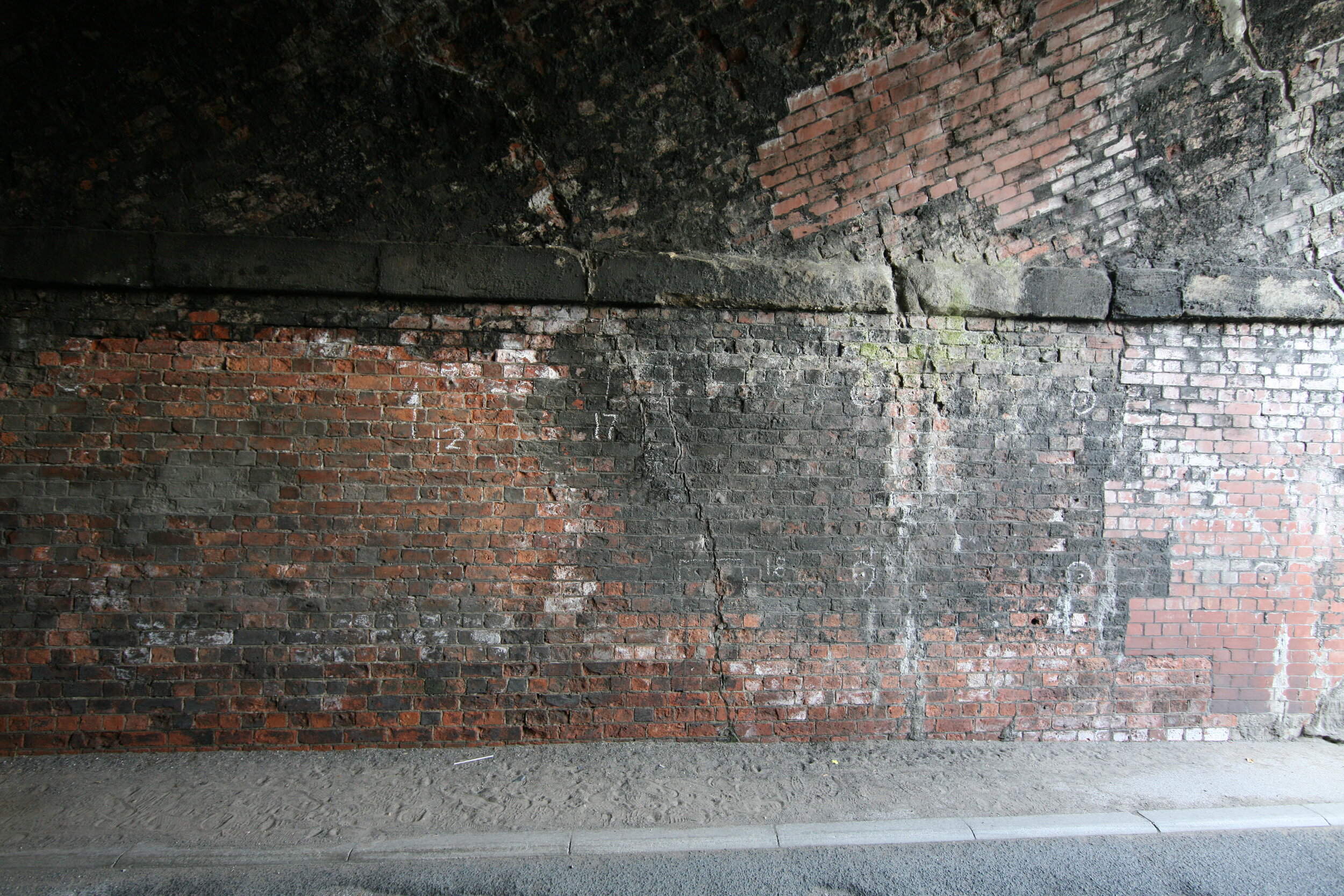
When we look down there we see cracks extending right to the ground and getting (ever so slightly) wider as they go.
With a similar picture on the opposite wall.

If we cut the arch with a horizontal plane to create a contour we see, as we did from a different direction further up, that the whole bridge has a sag towards the middle.

That is almost certainly caused by the weight of the embankment above and relatively soft ground below. Perhaps the Water Lane name is a clue?

At the portal, against the obtuse corner, a buttress has been added in the vain hope of containing the movement there. The top of the wall is being pushed back into the fill, creating cracks which gat noticeably wider to the front over a remarkably short distance. It would be interesting to see what the original wall looks like behind the buttress.

That’s quite a joggle in the joint too.
There is red brick patching in both portals. Less here than at the other end below. The cracking is quite a feature though, with cracks right through the stone string course and some step displacement too.
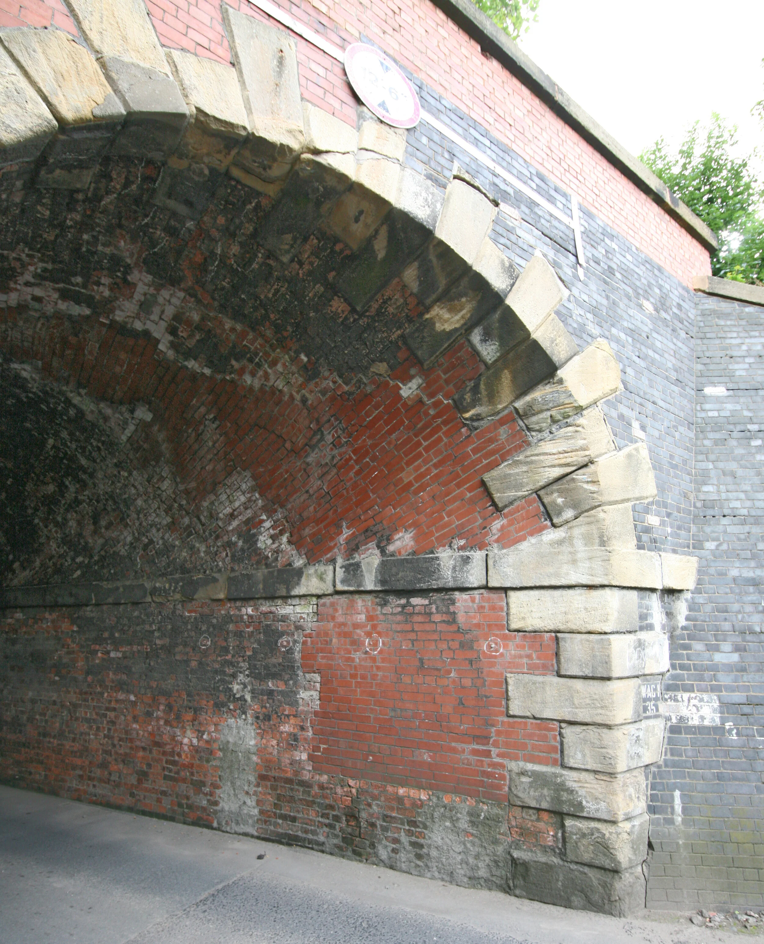
The angle here is slightly better showing the horizontal cracks in the spandrel wall as it is pushed in from the right. It runs down through the arch where it meets serious resistance from the other side, taking the line of weakest resistance.
I suspect that the patching is only skin deep and is therefore cracking through.

Looking back from inside, with shadows emphasising the steps, the extent and nature of what is going on becomes clearer. Notice the step in the string course at the right, which was surely replicated in the wall below and the arch above before patching. The crack presumably went up the middle of the patch in the wall and somewhere between the two fresh movements in the arch above.
Notice, also, how the beds in the original brickwork at road level dive away into the ground at the right where the forward lean has increased the ground pressure and encouraged settlement.

The distortion is shown well in this cross section, though it is worth noting that we had no survey on which to level the model. It is levelled by eye. I suspect this view should be rotated slightly to the left with more of a slope on the right and a definite lean back on the left.
There’s one more thing I want to look at. The cracks in the middle of the arch.
If we look at the layout on Google Maps we can measure the angle of skew and the position of the rails relative to the ends.

Compare that with the cracks in the roof ands I think they tie in closely with the edge of the track.

All that leaves the very difficult question of what might be done. Those acute ends could surely be tied back into the embankment, though doing so without further restricting the very narrow carriageway and footpath would be difficult. I think I would want to do something to be sure that the bottom of the keystone was secure. I expect that the crack rises as it goes in and there is a good anchor in there, but we can’t be certain without some sort of invasion. Perhaps a small core upwards near the back of the stone.
So far as monitoring is concerned, I think this might be a place for the old-fashioned invar tapes used by tunnelers. A hook in each wall, a tape with regular perforations to lock to and a dial gauge to finish the detail. To use modern tooling, nothing less than a Metrology instrument would do. Leica have a total station with very high precision. If we only need relative measurements, it will sit on a tripod and measure to a little spherical prism that is moved successively from base to base while the instrument follows.