
A PDF version is available here.
Here we go with year 12. Happy new year everyone. I am certainly hoping for better from 2022.
This bridge no longer exists. It was tested to destruction in 1986. I was there as an observer and I am able to correct some errors and misconceptions in the reporting. The canal it crossed was long closed and silted up so it doesn’t show on Google Maps, but you will find the village if you look. The canal was a Thos. Telford job and as well built as you might expect. I am looking back at it because I am in the middle of writing a book chapter on testing and monitoring masonry bridges. What follows will eventually find its way into the chapter but I thought it needed an outing before that.
The main point this month is my oft-repeated question “Is it a fair test”. In this case the answer is emphatically NO but that needs some expansion. I know that many of my readers are not engineers. I hope you will bear with me and perhaps understand a little about what engineering is.
Here is a general view of the bridge ready for testing, as it was when Fraser and I arrived after a long drive from Dundee.
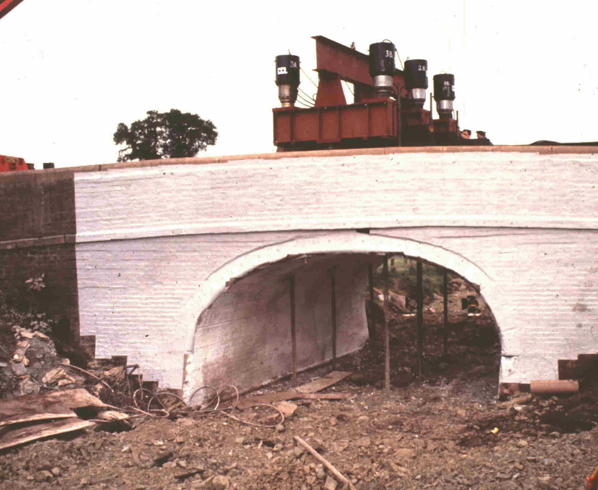
There is a lot to see here, much of which I didn’t notice till long afterwards. Perhaps I can leave that comment as a tease and come back to it as I did myself.
This was the fourth of a series of tests and was the first with this set of equipment. The large prestressing jacks (black jacks with shiny pistons) work in pairs, each reacting against a beam parallel to the span of the bridge. Below that, hidden from view, is a spreader pad, about 750mm in the span direction and 1.5m across the width. Three sets of that were aligned at about 1/3 span. They reacted against ground anchors, and it is obvious in the picture that the first of those is a long way from the near edge. That reflects the fact that the bridge is skew. The topmost beam is a catcher, an attempt to avoid dropping all that equipment when the bridge failed. Of course, it also introduced an unwanted stiffness between the jacks. More on that later, too.
Now let battle commence.

Those cables are very straight, so there is at least modest load applied and the bridge is beginning to respond. There are visible cracks through the voussoirs near this edge and slight spalling damage just outside each row of cables. The rippled and torn whitepaper is not actually white but covered in black squares of a size designed to exactly match the sensitivity of a film and lens combination. The surface was photographed repeatedly from a fixed location yielding (after considerable post-processing) contours of displacement on the surface. The spalling damage implies some rotation and that is confirmed by the slight opening of joints between the two rows of ties.
As the load increased, the damage became more severe.

Here, the spalling is much more severe and the joint opening between the ties is considerable. Note how the damage is even more severe on the far side.

Actually, this picture is slightly earlier. The spalling is largely confined between the ties and near the camera. Pushing the photo a little reveals just a bit more.

The stone on the floor is largely from between the tie bars. The piece on top of the pile is very thick. It seems to have fallen with little loss of material from above and may have split leaving a thin shell carrying the load.
Notice that, at both sides, the deflection between the walls is much greater than under them.

This picture shows the bridge very close to failure. Note how the ties close to the abutment are still tight while those nearer the camera are largely slack. The scale of loss of voussoirs is more obvious here. Note also the crack running down to the edge at the abutment following something close to the square line.

Once again, pushing the picture reveals a little more.

This picture shows the bridge after collapse and after a little modification by me and Fraser. Before we left the site we wanted to see what went on behind the arch. By pulling down a couple of voussoirs we exposed the brick back in inside the structure.
If you look back to the first photograph you will see a differentiating line on the spandrel wall and wing wall which marks the top of the backing. The backing is important because it is critical to the behaviour of the arch. The span is effectively reduced to just the central flat section.
I should also say a little about the shape because it was declared to be an elliptical bridge but clearly isn't. Three centred arches were used over canals because they provided more headroom for the horse towing the barge. It is perhaps worth drawing those two different shapes with the one to four span to rise ratio that this bridge has. First the actual three centred shape.

This is what a semi-ellipse looks like.

Here are the two curves superimposed.

As you can see the elliptical curve falls below the three centred at about the point where a horse would wish to walk.
So that brings us on to look at analysis. Those of you familiar with BA16 will know that many of the programmes used produced low results for Preston. That's largely because we were denied the right to include backing in the calculation. And here you can see the effect of that.

According to Archie-M the capacity would be about 6 tonnes.

Put in some backing and the result changes dramatically. Now live load stress dominates completely. Large parts of the line of thrust are straight and directly under the load it runs very close to the extrados over some distance. This comes much closer to representing what happened in the test. Several cracks opened between voussoirs under the load and there was considerable crushing at the intrados at points were the thrust touches. Archie is indicating a capacity of around 200 tonnes, though that is based on a mechanism forming rather than the stone crushing.

There is a version of Archie-M in development which shows stress blocks implied by the thrust line. Looking at that makes the situation a little clearer perhaps. Where the triangular blocks are short but wide the stress is concentrated close to the edge of the arch. There will then be significant rotation between the voussoirs.

Finally, a look at the elliptical shape. Here the capacity is shown as very slightly larger.
All of that leads to some thoughts about testing and bridge behaviour. The thing about testing is that you must be very careful to measure enough to know whether you are actually testing the right thing. It's my belief that the 1980s tests failed on that count.
As to the behaviour of this arch under load, perhaps the most interesting feature is the way the arch turns up at the edges under the load. I can't see how the walls would help that. They do prevent the load from being close to the edge of the arch. I believe though what this is telling us is that the distribution of load below the pads is negligible at this depth.
I think that will have to do for this month.