
A PDF version is available here.
Only very rarely do I post a bridge that I have yet to see myself. I have plenty in the files anyway but this month there is a broader context. Over the past year I have come to be closely associated with the family of Bel Anderson who worked with me last year between school and Uni. Since I live alone, having a family to be part of has been a great joy. They have been drawn into the society of gephyrologists and took these pictures for me last summer. I suspect this bridge will feature again because there is more to know than I have found out already.

Stanway is now part of the of the Gloucester and Warwickshire Steam Railway. It was built by the GWR just after 1900 on a new line linking Cheltenham with Stratford on Avon to allow GWR direct communication between the South West and Midlands. As you will see from the website it was not without mishap and when I do get to it myself, one question will be about the origins of that collapse.
The photo above shows a clear demarcation line at about half arch height, which says something about the backing. The general construction bears a close resemblance to Foalmead viaduct in Langport, Somerset, built a few years later to provide the more direct line to Exeter from Reading. Again, there is a clear demarcation line at mid height of the arch. And the structure seems to have been built with the same bricks and other details so the drawing we have of Foalmead should tell us something about Stanway.

Figure 1 Foalmead viaduct, Langport. Many have similar details.
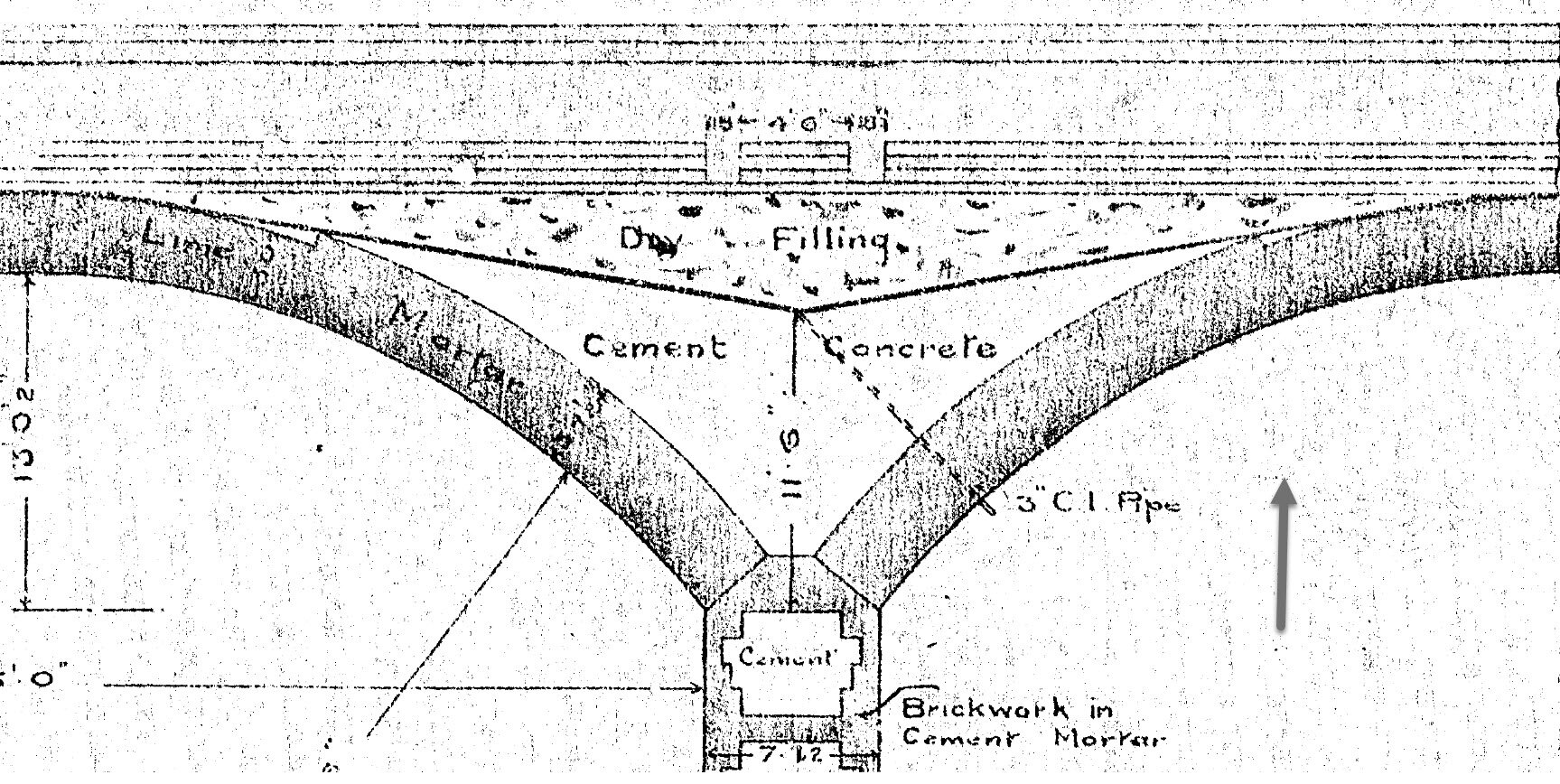
Figure 2 This drawing of Foalmead shows the likely internal construction of Stanway
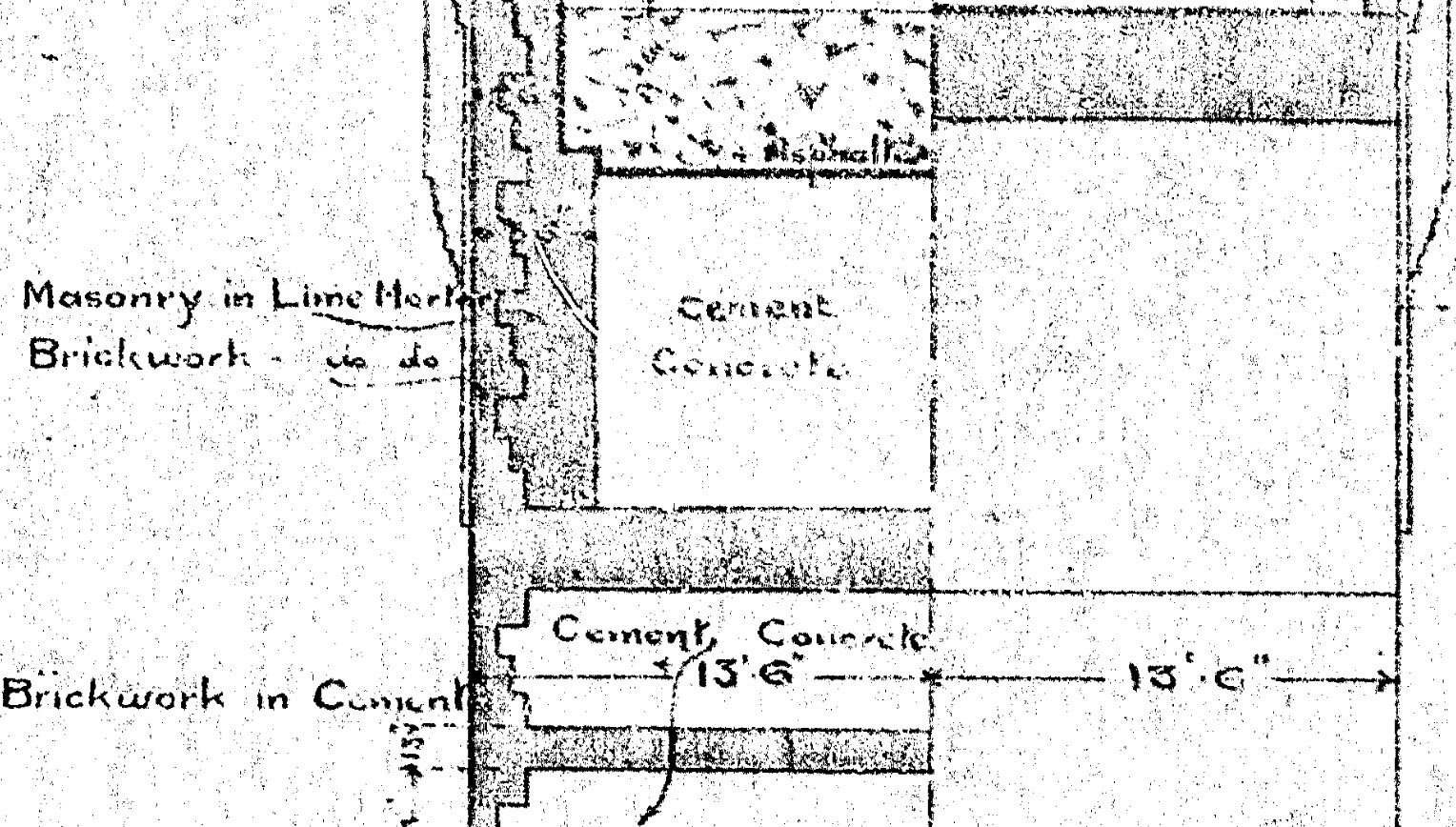
Figure 3 The cross section at Foalmead shows the concrete fill interlocked with the side walls. And then an internal buttress over the pier
There are, of course, some significant differences. The spans at Foalmead are longer and flatter because there wasn’t the height between the ground and railway for higher arches.

At Stanway, there are stone skewbacks. I suspect there is more to see in this picture if we lighten it a bit.

Indeed, we can certainly see a drain there.

Blowing it up, though, I am running out of detail. This will definitely need a closer look. That does look remarkably like a crack across the width, though it could just be the start of the rebuild after collapse.
Oh yes, I didn’t mention the collapse yet did I. Several arches collapsed during construction, leaving the piers and pier blocks standing.

That, too, needs much more investigation than I have time for just now, even if I wasn’t locked down.
But back to that closeup. It shows that the stone skewbacks are only the quoins. Stonework was obviously expensive.
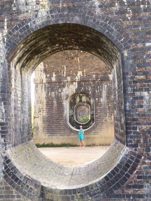
I could practically write a book about the content of this last picture.
First meet Joanna, surrogate daughter and carer. She gives the thing some scale.
Then look closer, first at the bottom. A definite crack, maybe two or three, in that invert, where the foundation has hogged. Interestingly, the crack at the crown, which is much more commonly noticed, is decidedly less prominent here.
Then, just half a brick in at each side of the gap is a vertical split. This is evidence of the load from the viaduct being supported mostly on the inside edge of the legs. There is likely to be corresponding damage on the outside where the lack of pressure and slight movement often leads to mortar and even brick loss.
And there we are, time to get on with the day job.